Building a Smart Train Departure Countdown Display
May 5, 2025 · Kamran Azari · ESP32 · FreeRTOS · IoT · C++
Watch the Demo
More projects on my YouTube channel.
The Problem: Mental Math Every Morning
Your train leaves at 08:14. The station is a 9-minute walk. You need a minute to lock the door. So you should leave at 08:04. But you haven't finished your coffee. And is the bike outside today? That's 4 minutes — so maybe 08:09.
This small calculation runs in the background of every commuter's brain, every single morning. It's not hard, but it's a constant low-grade tax on your attention. Miss the window by 30 seconds and you're jogging. Leave too early and you stand in the cold.
I wanted to solve it with one glance at the wall.
The Idea: Count Down to When You Leave, Not When the Train Departs
Every train app already shows you departure times. What none of them do is answer the actual question: when do I put on my coat?
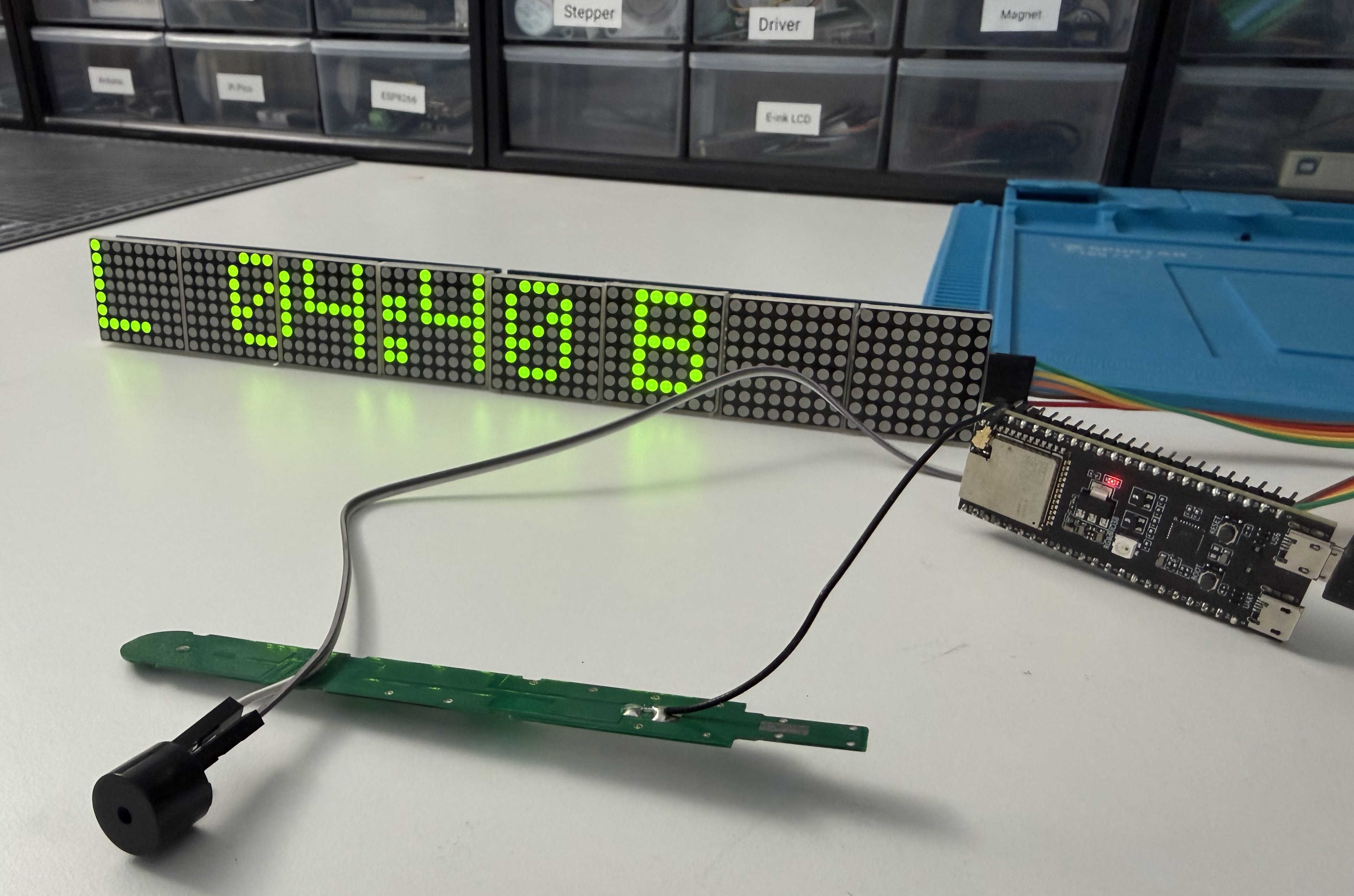
This device answers exactly that. The display shows a live MM:SS countdown to the moment you need to walk out the door — already accounting for the distance to the station. When it hits zero, you leave. No mental math required.
Hardware Overview
Bill of Materials
Required
| Component | Notes |
|---|---|
| ESP32-S3-DevKitC-1 | Dual-core 240 MHz, 8 MB flash, built-in WiFi |
| 2× MAX7219 FC-16 modules | Chained together → 64×8 pixel dot-matrix display |
| 5V / 3A USB power supply | The display draws up to 2 A at full brightness |
| 1000 µF / 16V capacitor | Place on 5V rail close to the first module |
Optional
| Component | Purpose |
|---|---|
| DS3231 RTC module | Time continuity during WiFi outages |
| Passive buzzer | Audio alerts (configurable, off by default) |
| RGB LED (common cathode) + 3× 220 Ω | Visual urgency indicator |
| Rotary encoder + button | Physical transport mode selection |
| 3× momentary push buttons | Refresh, mode switch, factory reset |
Wiring (Key Connections)
MAX7219 Display  →  ESP32-S3
  DIN (MOSI)     →  GPIO 11
  CLK (SCK)      →  GPIO 12
  CS  (LOAD)     →  GPIO 10
  VCC            →  5V   (separate rail — NOT 3.3V)
  GND            →  GND

DS3231 RTC (I²C, optional)
  SDA            →  GPIO 1
  SCL            →  GPIO 2

RGB LED (common cathode)
  Red            →  GPIO 18 + 220 Ω
  Green          →  GPIO 8  + 220 Ω
  Blue           →  GPIO 3  + 220 Ω

Buzzer (PWM)     →  GPIO 17
Buttons          →  GPIO 7 / 15 / 16  (to GND, internal pull-up)
The MAX7219 chain runs on 5V. Keep the power traces short and put the 1000 µF cap as close as possible to the first module — display glitches are almost always a power supply issue.
System Architecture
The diagram below shows how the main components interact. The ESP32 runs two concurrent FreeRTOS tasks; a binary semaphore ensures the display never reads corrupt data during an API fetch.
How the Countdown Works
The device fetches the next departures from your station via the NS Reisinformatie API every 2 minutes. For each departure it calculates the time you need to leave:
leave_time = departure_time - (travel_time + buffer_time) * 60
If your station is a 9-minute walk and you set a 2-minute buffer, the display starts counting down 11 minutes before the train leaves. When it hits 00:00, that's your cue.
The API returns the planned departure time, not the real-time delay. That's intentional: you plan your life around the schedule, not live delays. Delays are surfaced separately in the departure data but don't affect when the device tells you to leave.
There's also a 30-second grace period: if a train departs within the next 30 seconds the device doesn't immediately skip to the next one, preventing a jarring jump right when you're deciding whether to sprint.
Walk vs Bike: Distance Is the Key Variable
The single most important configuration parameter isn't the station code — it's how long it takes you to get there. That number changes based on how you travel.
The display alternates every 5 seconds between Walk and Bike mode (a Bus mode is also available). Each has its own independent travel time that you set once. At a glance you can see both options and decide which applies today.
If the bike isn't available, the device gracefully shows only the walking countdown. If neither mode has a catchable train, it waits and retries silently.
Why Display Size Actually Matters
The most underrated design decision in this project is the display choice. A small LCD or OLED is fine for a desk gadget you lean in to read. This is a room display. The whole premise falls apart if you have to walk up to it.
Two chained MAX7219 FC-16 modules give 64×8 pixels total — a wide strip of large blocky digits readable from several meters away, in daylight, without glasses. No backlight glare, no color calibration, no viewing angle issues. The dot-matrix aesthetic is purely practical.
The Non-Blocking Design Challenge
Here's the embedded systems problem that took the most thought: an HTTPS round-trip to the NS API takes 2–3 seconds (SSL handshake + JSON parsing). On a microcontroller, doing that on the main thread freezes everything — the display stops ticking, buttons stop responding. That's unacceptable.
The solution uses a FreeRTOS background task and a binary semaphore:
// Main loop — runs every second
void loop() {
    if (xSemaphoreTake(nsMutex, 0) == pdTRUE) {
        // Got the mutex: read fresh departure data
        cacheWalk = nsApiClient.getNextDeparture(WALK, config.walkTime);
        cacheBike = nsApiClient.getNextDeparture(BIKE, config.bikeTime);
        xSemaphoreGive(nsMutex);
    }
    // Always update display — from cache if mutex was busy
    updateDisplay(cacheWalk, cacheBike);
}

// Background fetch task — created every 2 minutes
void fetchTaskFn(void *) {
    xSemaphoreTake(nsMutex, portMAX_DELAY);  // blocks main only during HTTPS
    nsApiClient.fetchDepartures(config.stationCode, 10);
    xSemaphoreGive(nsMutex);
    vTaskDelete(NULL);
}
main.cpp ns_api_fetch_esp32.cpp
The mutex is held only during the actual HTTPS transaction. The main loop uses a non-blocking xSemaphoreTake(..., 0) — if the fetch is in progress, it simply reuses the last cached timestamps and keeps the countdown ticking. The display never blanks or freezes.
Urgency States and Alerts
The device knows five urgency levels and the hardware responds accordingly:
| State | When | RGB LED | Display |
|---|---|---|---|
| Safe | > 10 min | 🟢 Green | MM:SS, calm |
| Ready | 5–10 min | 🟡 Yellow | MM:SS |
| Time to Go | 2–5 min | 🟠 Orange | MM:SS + buzzer once |
| Urgent | < 2 min | 🔴 Red (blinking) | Animated icon + seconds |
| Departed | Passed | Off | Next train |
When the countdown drops below 60 seconds, the rightmost display module switches from text to a walking or cycling icon (depending on the active mode). It's a visual signal that standing around is no longer an option.
The buzzer plays distinct tone patterns for each alert type — a single long beep at "time to go," two short beeps at urgent — and is disabled by default. On power-on it always plays a triple beep regardless of settings, confirming the hardware is alive.
Web UI and Configuration
Everything is configured through a local web UI hosted directly on the device at http://<device-ip>/. No app, no account, no cloud. The page auto-refreshes the live status every 2 seconds.
The UI shows both walk and bike countdowns live, WiFi signal strength, heap memory, uptime, and a "Fetch Now" button to trigger an immediate refresh. Configuration options include station code, all three travel times, buffer time, and alert preferences. Credentials (API key, WiFi password) are masked and stored in the ESP32's NVS flash — never in source code.
REST API for Smart Home Integration
The device exposes a small REST API with CORS headers, making it straightforward to integrate with Home Assistant, Node-RED, or any other automation platform.
GET /api/status      → full system snapshot
GET /api/departures  → next walk + bike countdowns
GET /api/config      → current config (secrets masked)
POST /api/config     → update any config fields
POST /api/transport  → switch mode { "mode": "bike" }
POST /api/fetch      → trigger immediate data refresh
Example response from GET /api/departures:
{
  "fetchInProgress": false,
  "departures": [
    { "mode": "walk", "secondsUntilLeave": 312, "direction": "Den Haag Centraal" },
    { "mode": "bike", "secondsUntilLeave": 480, "direction": "Den Haag Centraal" }
  ]
}
All API handlers read from a cached status struct that the main loop writes every second. The async web server never touches the departure mutex directly — no risk of blocking the display while serving a web request.
Unit Testing Without Hardware
One pattern I'm proud of here: all the core logic — countdown calculation, state machine, NS API parsing, configuration validation — is tested in a native desktop environment. No ESP32 needed.
pio test -e native          # run the full test suite on your Mac/Linux
pio test -e native -v       # verbose
pio test -e native -f test_countdown_calc  # single suite
test_countdown_calc.cpp test_ns_api.cpp platformio.ini
Hardware-specific code (*_esp32.cpp) is excluded from the native build via PlatformIO's build_src_filter. Stub implementations replace the display, buzzer, buttons, and WiFi for the test environment. This means the business logic can be iterated and tested fast, without flashing the device every time.
Full Feature List
- Live MM:SS countdown to when you need to leave (not when the train departs)
- Separate Walk, Bike, and Bus modes with independent configurable travel times
- Display alternates between modes every 5 seconds automatically
- Fetches live NS Railways API data every 2 minutes in the background
- Display never freezes during API calls — FreeRTOS mutex design
- 5-state urgency system: Safe → Ready → Time to Go → Urgent → Departed
- Animated icon on urgent mode (<60 s) — walk or bike figure
- RGB LED urgency indicator (green → yellow → orange → red blinking)
- Optional buzzer with distinct tone patterns per alert level
- Local web UI — no app, no account, self-hosted on device
- REST API with CORS — ready for Home Assistant, Node-RED, shell scripts
- NTP time sync with Amsterdam DST handling (CET/CEST)
- Optional DS3231 RTC fallback for accurate time during WiFi outages
- All config persists across reboots via ESP32 NVS flash
- Credentials stored securely in flash — never in source code
- Factory reset via long press or web UI
- Physical mode cycling via button press
- Unit tests runnable on desktop with no hardware (PlatformIO native env)
- Rotary encoder support for future UI navigation
What I Learned
The hardest part wasn't the API integration or the display driver — it was the concurrency. Getting the mutex pattern right so the display never shows stale or corrupted data while an HTTPS fetch is in progress required a few iterations. The key insight was to cache only primitive values (Unix timestamps, string copies) before releasing the mutex, so the main loop can safely recalculate the countdown from those without holding the lock.
The other lesson: power supply matters more than you expect. Two MAX7219 modules at full brightness pull close to 2 A. Without the 1000 µF cap on the 5V rail, the ESP32 would reset when the display lit up. A €0.10 capacitor in the right place saved hours of debugging.